
All Posts By

Claire Johnson

Why Getting Specified Early Is the Most Important Decision in a Window Automation Project

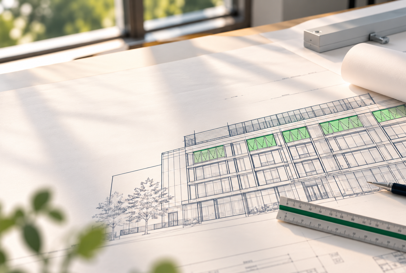
Facade elevation drawing showing automated window openings at design stage

On many projects, window automation is one of the last things to be resolved. The facade is detailed, the window system is selected and the mechanical strategy is set. Only then does someone ask how the high-level windows are actually going to open.

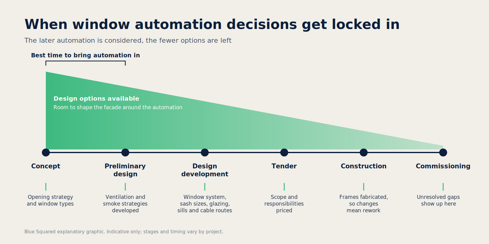
By that point, most of the decisions that determine whether an automated window performs well have already been made. The sash size and glazing set the load the actuator has to move. The frame profile and sill detail decide whether the actuator can be concealed. The position of the opening decides whether it needs restriction or safety sensing. Cable routes, control logic and the interfaces with the BMS and fire system have either been allowed for or they haven’t.

None of those decisions are made with the actuator in mind, but every one of them constrains what the actuator can do. So the most important decision in a window automation project usually isn’t which actuator to use. It’s when the automation is brought into the design.

This article looks at what gets locked in early, why it matters for ventilation and smoke-control performance, and what changes when automated openings are specified at design stage rather than resolved after the facade is finished.

The actuator is chosen from the window

An automated window is a system made up of the window or louvre, the actuator, its brackets, the controls and sensors, and the building systems it connects to. The actuator is the visible part, but it’s selected from the window rather than from a catalogue.

Selection is a calculation. It starts with the opening type and direction, the sash dimensions, whether the unit is single or double glazed, the glass thickness and how far the sash needs to open. From those, the sash weight and required stroke are worked out and a suitable actuator is proposed. Wide or heavy sashes are often better served by two actuators working at the quarter points than by one larger unit at the centre. We cover actuator selection and free area calculation in more detail in Window Actuators Explained.

Every one of those inputs is a design decision made by the architect or facade team. If they’re made without the automation in mind, actuator selection becomes a matter of making the best of what’s been drawn. Sometimes that’s straightforward. Sometimes it means a larger or more visible actuator than the design intended. It can mean extra actuators on a sash that was never detailed for them, or an opening that can’t quite achieve the free area the ventilation strategy depends on.

What gets locked in before the automation is considered

Frame profile and sill detail
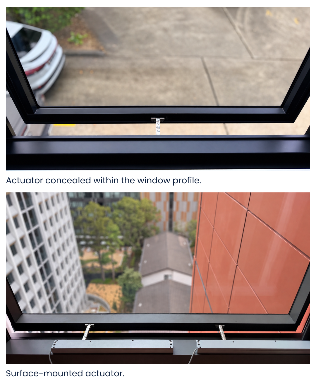
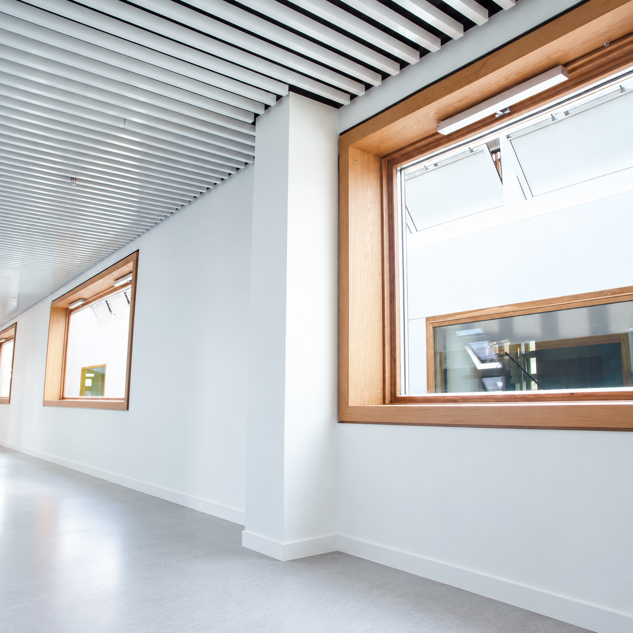
Whether an actuator can be concealed depends on the window system. Some proprietary aluminium window systems have an internal sill space that accommodates a chain actuator without modification. Others don’t, and the actuator ends up surface mounted.

The chain stroke matters here too. A longer chain needs larger links to maintain its integrity, which means a larger housing to conceal it when withdrawn. The window profile also uses up some of the chain’s travel just bridging the gap from the actuator’s fixing point to the sash, so the clear opening is less than the stroke itself. If a concealed, low-profile actuator is part of the design intent, the window system and actuator need to be considered together before the system is selected.

Opening position and height

Where an opening sits in the building changes the scope of the automation. High-level windows that occupants can’t reach are generally the simplest case. Low-level openings that people can reach need a different approach. That can include restricting how far the window opens, adding presence sensing that stops the window moving when someone approaches, and a risk assessment covering entrapment and safety.

Each of those affects cost, hardware and the control design. They’re much easier to allow for when the opening strategy is being set than after the window schedule has been issued.

Cable routes

Actuator cabling has to reach every opening. A window profile can often act as a concealed conduit, which avoids surface-mounted trunking. However, the window or curtain wall fabricator needs to prepare the profiles with grommets and draw wires in advance. Once the frames are fabricated, that option has usually gone. What’s left is a visible cable run that nobody drew.

Controls and interfaces

Automated openings can be controlled by wall switch, controls, app, sensor, time schedule, BMS or fire alarm signal, and often by a combination of these. Sensors for wind, rain, temperature and CO2 may all feed into the control logic. Where the system connects to a BMS, the protocol and level of integration need to be agreed with the controls contractor. Where two-way communication is used, the BMS can receive position and fault feedback rather than simply sending open and close commands.

Each of these is an interface between trades. It needs to appear in the electrical, mechanical and fire documentation, not only in the window specification.
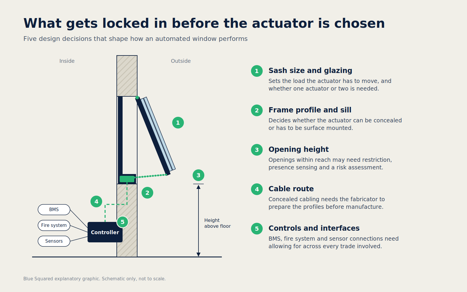
Diagram showing the window design decisions that affect automated window performance

The ventilation strategy depends on the opening delivering what was designed

A natural or mixed-mode ventilation strategy is designed around openings achieving a particular free area and operating in a particular pattern. The mechanical engineer’s calculations assume the windows will open as far and as often as the strategy needs.

Free area depends on more than the size of the window. It depends on the opening geometry, the chain stroke, and any reveal or sill that restricts the opening. It also depends on how the free area is calculated. The throat formed at the leading edge of the sash is usually the starting point, with the side triangles counted only where the strategy allows. Actuators with controllable stroke can be set to open to a specific position rather than simply running to full travel. That helps, but only if the required opening has been defined in the first place.

The control logic matters as much as the hardware. When a purge cycle runs, and how windows hand over to mechanical ventilation in a mixed-mode building, are design decisions that shape how the actuators are scheduled and how the controller talks to the BMS. When the window specification and the ventilation strategy are developed separately, the gap between them tends to appear at commissioning, which is the most expensive point to find it.

Smoke control leaves even less room for late changes

Where an automated window or louvre forms part of an engineered smoke-control strategy, its required performance, fail-safe behaviour and interface with the fire system are set by the project’s fire engineer. The product doesn’t decide these things, and they need project-specific assessment rather than assumptions carried over from another building.

Timing matters even more here. WindowMaster’s guidance on smoke vents tested to EN 12101-2 treats the declared performance as belonging to the finished vent, meaning the window and actuator together as tested, not to the actuator alone. How that European framework applies on a particular Australian project is a question for the fire engineer and certifier. The practical point holds either way: on a smoke vent, a late change to the window system, sash size or actuator is not a like-for-like swap.

Bringing the automation into the design early means the combination can be confirmed while there is still time to adjust it.

What early specification looks like in practice

Design-stage input from an automation specialist is practical rather than theoretical. On a typical project it can include:

  • actuator sizing and free area calculations from the window information available
  • specification wording that describes the complete system rather than a generic “motorised window operator”
  • CAD files the design team can place straight into their drawings
  • a view on whether a standard bracket will suit, or whether a bespoke bracket or adaptation is needed
  • an approach to safety for any openings within reach
  • a clear split of responsibilities between the facade contractor, electrical contractor, controls contractor and fire trades

Non-standard openings benefit most. An unusual sash, a heavy rooflight or an opening in an awkward location can be assessed for feasibility before it’s drawn into the facade, rather than after it’s been built.

The main benefit shows up at tender. When the documentation describes a coordinated system, tenderers price the same scope, and fewer gaps are left to be resolved through RFIs, variations or on site. Clear responsibility at the boundaries between trades matters most: who fixes the brackets into the frame, who runs and terminates the cabling, and who tests the interface with the fire panel or BMS.

When is early enough?

Ideally, automation input starts at concept or preliminary design, when window types and the opening strategy are being set. It should also run alongside the mechanical and fire engineers as they develop the ventilation and smoke-control strategies. At the latest, it should happen before the window system is selected and the facade details are developed, and well before tender documentation.

Complete information isn’t needed to start. Approximate window sizes, opening types, locations and the intended function of each opening are enough to begin sizing actuators and identifying the questions that need answering.

Late involvement isn’t a lost cause, but the options narrow. The same is true of work on existing buildings. Where a building already has window automation, an extension will often need its own system rather than a tie-in to the existing one, and that’s worth establishing at the outset.Diagram showing the window design decisions that affect automated window performance
Questions to resolve before the facade is locked in

Before the window system and facade details are finalised, a design team should have answered a few questions. What are the opening type, direction, dimensions and glazing of each automated opening? What does each opening do: comfort ventilation, purge, mixed-mode operation, smoke control, or more than one of these? What free area does the strategy require, and can the chosen profile, reveal and sill achieve it? Are any openings within reach of occupants, and what restriction or sensing will they need? Will the actuators be concealed, and does the window system allow it? Where will the cabling run, and does the fabricator need to prepare the profiles? How will the system be controlled, and what are its interfaces with the BMS and fire system? Finally, which disciplines need to confirm these decisions before they’re locked in?

Conclusion

An automated window only performs as well as the decisions made around it. By the time actuator selection comes up on many projects, the sash, glazing, profile, sill, cable routes and control strategy have already been decided, often without the automation in mind. Specifying early means those decisions support the automation rather than constrain it. The result is a design that achieves its ventilation and smoke-control intent, a tender that prices a complete scope, and an installation with fewer surprises.

Blue Squared offers no-cost design-stage consultation for architects and engineers, including actuator sizing, free area calculations and specification support. If you’re working on a project with automated windows, louvres or smoke vents, get in touch early. It costs nothing and saves a lot. Contact the team at info@bluesquared.com.au.
Trap Hazards in Automated Windows: What Needs to Be Considered

window automation trap hazard

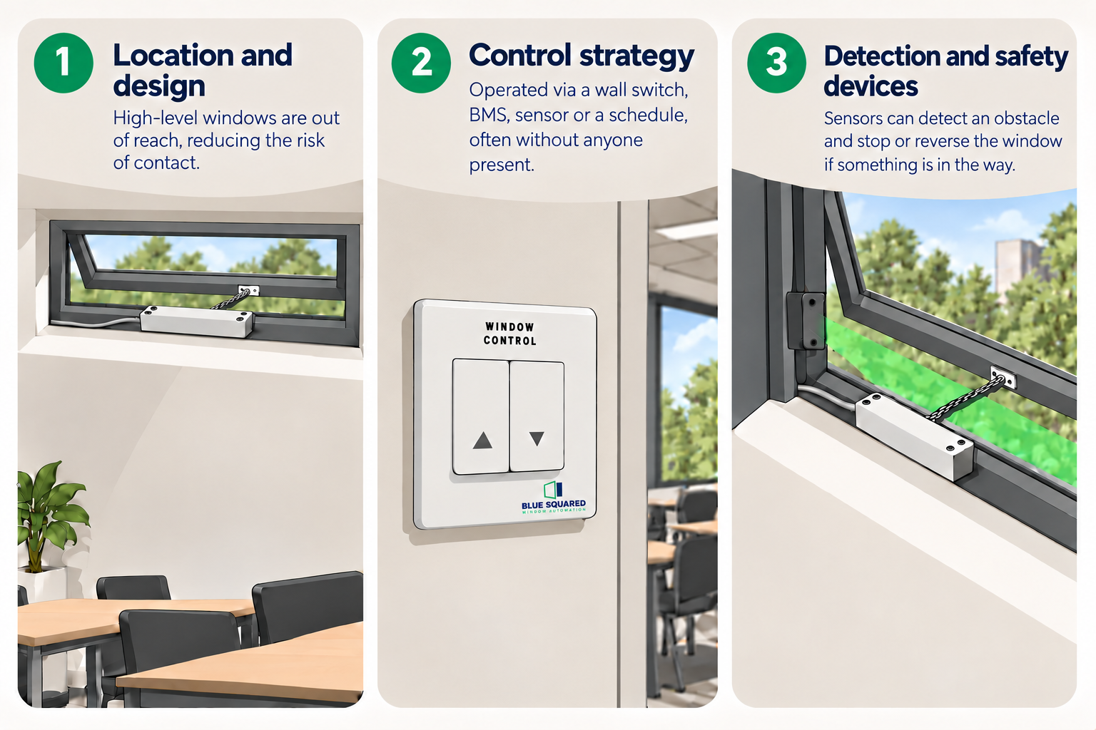
An automated window doesn’t need someone standing in front of it to open or close it. That’s the point of automating it, but it also raises a question worth resolving properly at design stage: what stops the window closing on something, or someone, in its path?

This is generally referred to as trap hazard mitigation, the methods used to reduce the risk of an automated opening closing on an obstruction. It’s not a single product or a tick-box requirement. Depending on the project, it can be addressed through where the window sits and who can reach it, how the control system schedules and times movement, or the addition of a sensor that monitors the closing path directly. Which of these applies, and how many are needed together, depends on the specific opening, and getting that judgment right is as much a part of specifying automated windows as choosing the correct actuator.

Why automation changes the risk

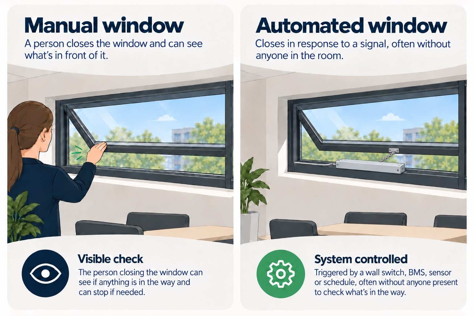
A manually operated window is opened and closed by a person who can see what’s in front of it. If a hand is resting on the sill, a cord is hanging across the opening, or someone is leaning through the frame, the person closing the window notices and stops. An automated window can be triggered by a wall switch, a building management system, a sensor, or a schedule, often without anyone in the room at the time, and without that instinctive check taking place.

That doesn’t make automated windows inherently unsafe. It does mean the question a person answers instinctively when closing a window by hand, is anything in the way, needs to be answered by the system instead. Where an opening is genuinely low risk, that answer can come from where the window is and how it’s used. Where it isn’t, the system needs another way to check.

This is a genuinely different design problem to specifying the actuator itself. An actuator is selected against the window’s geometry, weight and required stroke, questions that can largely be answered from a set of drawings. Trap hazard mitigation is answered against how the space around the window is actually used, who can reach it, when it’s occupied, and what else is likely to be near the opening while it moves. That’s a question about the building and its occupants as much as the window, which is why it needs its own consideration rather than being assumed to follow automatically from the actuator specification.

It’s also worth separating this from the related, but distinct, question of fall risk at low-level openings. Restricting how far a low-level window can open is generally about preventing someone falling through it or an object dropping from it, particularly where the opening faces a footpath or thoroughfare. Trap hazard mitigation is about what happens on the way to that restricted position, or on the way to fully closed, not the maximum opening itself. A project can need to address both, and they’re usually resolved through different parts of the specification.


Three ways trap hazard risk is addressed

Window positioning and reach

The simplest form of mitigation is removing the opportunity for contact altogether. A high-level, out-of-reach opening carries a fundamentally different risk profile to one at head height in a corridor or above a walkway. Where an automated window is genuinely inaccessible to occupants, that positioning is itself doing a lot of the risk-reduction work, before any control logic or sensor is added.

This is one of the reasons opening type and location get resolved early in a specification. A top-hung, outward-opening window at high level isn’t just a natural ventilation preference, it also tends to sit well clear of anywhere someone could be caught by its movement. The same logic applies in reverse: a low-level opening in a corridor, foyer or publicly accessible facade needs to be treated differently from the outset, rather than having risk mitigation added on as an afterthought once the window type has already been chosen.

Control logic and timing

Where a window is within reach, or operates in a space that’s occupied while it moves, the control system itself can reduce risk. This can include scheduling movement for times a space is known to be unoccupied, using slower or more controlled closing speeds rather than a single fast stroke, and building in obstacle-detection at the actuator or controller level.

WindowMaster’s MotorLink-enabled actuators, for example, include an obstacle-detection function that reverses the actuator if it meets resistance while closing. That’s a useful layer of protection, but it’s a mechanical response to resistance already being met, not a substitute for checking the path is clear before the window closes fully. On its own, it’s rarely the whole answer for a genuinely accessible opening.

Control logic also needs to account for what happens when something goes wrong elsewhere in the system, a power interruption, a fault, or a manual override triggered by a building occupant or the fire system. A window that’s mid-cycle when power is lost, or that’s commanded to close by an override while someone is nearby, still needs to behave safely. This is one of the reasons trap hazard mitigation is considered alongside the control strategy as a whole, rather than treated as a single add-on feature.

Sensing the closing path directly

For openings where positioning and control logic aren’t enough on their own, typically low-level windows in occupied or publicly accessible areas, a sensor can be added that monitors the closing path itself and signals the control system to stop, or reverse, before the window makes contact.

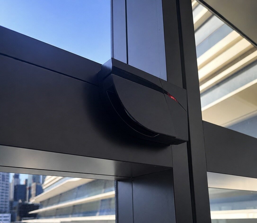
A laser sensor is one way this is done. In general terms, this kind of sensor scans the plane the window is closing through, using the reflection of the laser to detect whether the path is clear, and reports back to the controller in real time rather than waiting for the actuator to meet physical resistance. This is a meaningfully different kind of check to obstacle-detection at the actuator: it’s designed to stop the movement before contact occurs, not after.

Not every automated window needs this. It depends on where the window sits, how accessible it is, and how it operates within the wider system. But it’s a good example of the kind of thinking a proper trap hazard assessment involves: the movement itself is only part of the picture, and what happens if something’s in the way needs to be considered too.

Why this isn’t a standard answer

It would be simpler if every automated window needed the same level of protection, but that’s not how the risk actually works. A high-level window with no public access underneath it carries a different risk profile to a low-level, publicly accessible opening in a busy building, and a window opening onto a private plant area is a different case again to one opening above a public foyer or thoroughfare. Occupancy pattern, opening height, whether the space is public or restricted, and how the window fits into the broader automation and control strategy all affect what’s appropriate.

Specifying a sensor on every automated window regardless of risk isn’t a genuinely safer default, either. It adds cost and complexity to openings where the risk was already low, and it can create a false sense of security elsewhere on the project if a team assumes the same approach applies everywhere without checking. Equally, assuming positioning alone is sufficient because a similar-looking window on another project didn’t need a sensor can miss something specific to this building, a change in floor level, a walkway added at design development, or a change of use in the space below.

A trap hazard risk assessment is a project-specific exercise rather than a specification default. It’s carried out for the actual opening, in its actual location, rather than assumed from a similar-looking window on another project.

A recent example

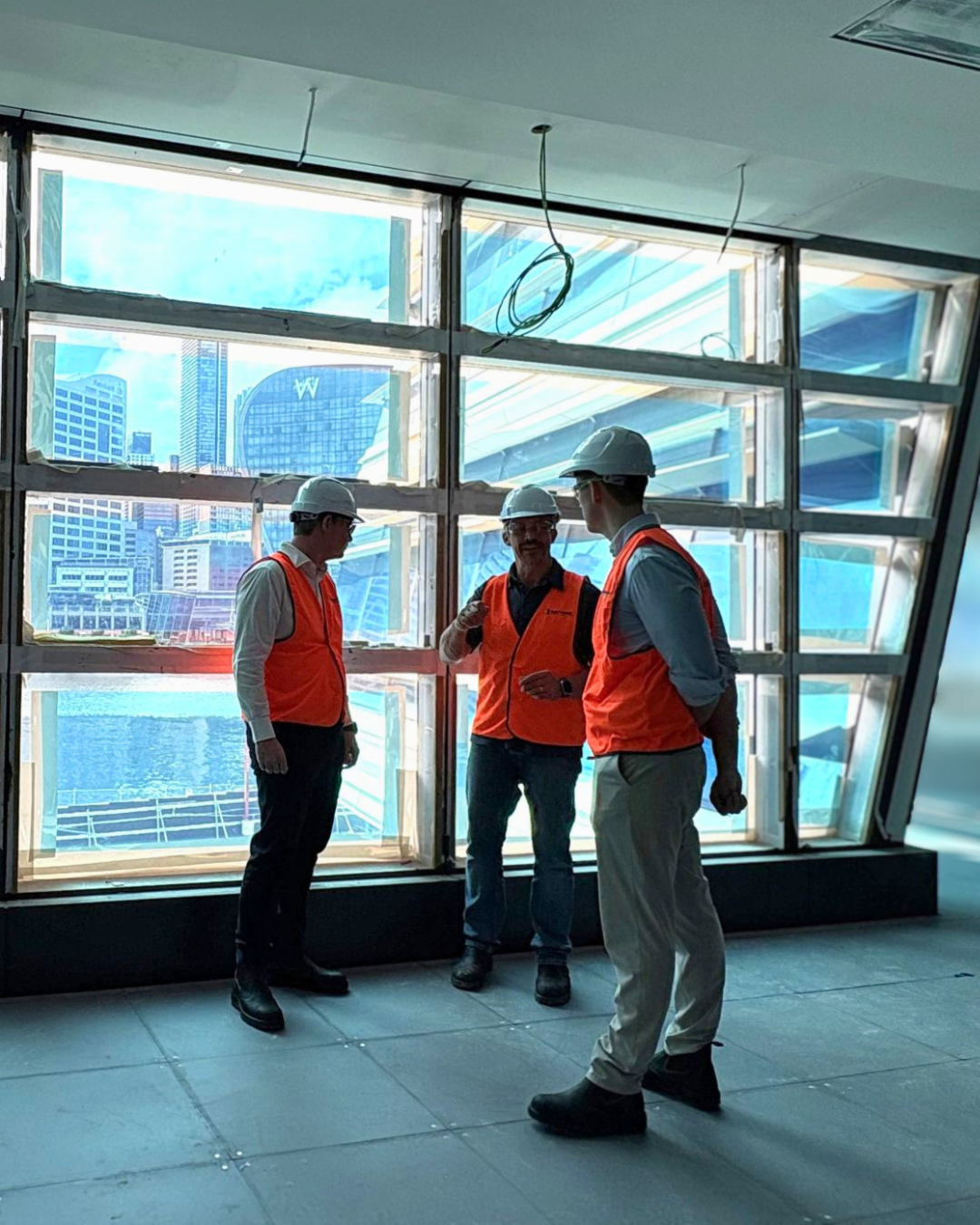
On the Harbourside Redevelopment in Darling Harbour, Sydney, Blue Squared is working alongside facade contractor Chevalier Aluminium on a project where low-level automated windows form part of the specification in an area with public access. A BEA LZR-FLATSCAN laser sensor is being used to monitor the closing path of these openings, signalling the control system to stop the actuator if it detects an obstruction before the window fully closes.

This project is a useful illustration of the principle rather than a template to copy directly. The same solution won’t automatically apply to every low-level opening; it reflects what the risk assessment for this specific location requires, including how accessible the openings are, how the space around them is used, and how the windows fit into the wider automation and control system for the building.


Coordination across the project team

Trap hazard mitigation rarely sits with a single discipline. The architect and facade consultant generally set the opening type and location that determine baseline accessibility. The mechanical engineer or facade automation specialist works through the control logic and, where required, the sensor and its interface with the controller. The electrical contractor runs and terminates the wiring for that sensor alongside the actuator cabling. And the builder or head contractor needs to know, well before installation, whether a low-level opening on the project requires this additional scope so it can be programmed and priced correctly rather than discovered on site.

Where this coordination happens late, it tends to show up as a late change: a sensor added after the window and control system have already been detailed, rather than designed in from the outset. That can mean re-running cable routes that were already fixed, revisiting a bracket or mounting detail that didn’t allow for a sensor housing, or a controller that needs an additional input it wasn’t originally specified with. None of this is difficult to accommodate if it’s known about early, but each of these becomes a variation, rather than a line item, once the design is locked and the trades are on site. Resolving it during design avoids that rework and gives every discipline a clear view of what’s required before tender.

Testing, commissioning and documentation

Specifying the right combination of positioning, control logic and sensing is only half the job. Whatever mitigation is used needs to be tested and confirmed working before the building is handed over, not simply assumed to be functioning because it was installed correctly on paper.

For a sensor-based solution, this generally means confirming the sensor detects an obstruction reliably across the relevant part of the closing path, that the signal to the controller correctly stops or reverses the actuator, and that this behaviour is repeatable rather than a one-off test result. Where control logic or scheduling is the primary mitigation, commissioning needs to confirm the window actually behaves as intended under the conditions it will operate in, not just under test conditions.

This should be documented as part of the project’s handover package, so a building owner or facilities team understands what mitigation is in place on which openings, and so it can be checked again if the control system or actuator is ever serviced or replaced later in the building’s life. A sensor that isn’t included in that documentation is easy to overlook during future maintenance, particularly if the person servicing the window years later wasn’t involved in the original design.

A practical takeaway for design teams

Trap hazard mitigation works best when it’s considered alongside the rest of the automation design, not bolted on afterwards. Questions worth resolving early include:

Where does the window sit in the building, and is it genuinely accessible to occupants or the public? Is the space occupied while the window is scheduled to move, and can timing reduce that overlap? Does the opening warrant a sensor that monitors the closing path directly, in addition to any obstacle-detection built into the actuator? Who is responsible for specifying, supplying and wiring that sensor, and how does it interface with the controller? How will the mitigation be tested and documented at commissioning, so it’s confirmed working before handover rather than assumed?

Leaving these questions until installation tends to mean retrofitting a solution around a design that didn’t account for it, which is a harder and more expensive way to solve the same problem.

Conclusion

Trap hazard mitigation isn’t a single product decision. It’s a combination of where a window sits, how the control system schedules and manages its movement, and, where warranted, a sensor that checks the path is clear before the window closes. Getting the combination right for a specific opening is what a proper risk assessment is for, and it’s worth carrying out before the window and controls are locked into a specification rather than after.

Blue Squared can carry out a trap hazard risk assessment as part of the design and specification process for a commercial automated window project, working through positioning, control logic and sensing needs for the specific openings involved, and coordinating the outcome with the rest of the project team before it needs to be resolved on site.

If you’re working through trap hazard mitigation on a current project, get in touch with the team at Blue Squared.

Window Actuators Explained: What They Do and How to Choose the Right One

how to choose the right window actuator to automate awning windows or louvre windows

Specifying an automated window is not simply a matter of choosing a motor with enough force to push a sash open. The opening type, the geometry of the window, the weight of the glazing, how far the sash needs to travel and the ventilation strategy the window is serving all affect which actuator is right for the job – and getting it wrong shows up later, either as an undersized system straining against a heavy sash or an oversized one that’s unnecessarily expensive and awkward to conceal.

This article sets out what a window actuator actually does, the main types available, how selection and free-area calculations work, and the practical considerations that should be resolved before a system is chosen, whether the application is comfort ventilation in a classroom, mixed-mode ventilation in an office, or an automatic opening vent as part of a building’s smoke-control strategy.

What a window actuator does

A window actuator is the motorised replacement for a manual winder or handle. Instead of a person opening and closing a sash by hand, the actuator does it on command, from a wall switch, a handheld remote, an app, a building management system, a sensor, or a signal from the fire system.

The actuator itself is only one part of a wider system. It works alongside the window or louvre, the brackets that mount it, the sensors and controllers that tell it what to do, and,  on many commercial projects,  the building’s fire strategy and BMS. Treating the actuator as an isolated component, separate from that system, is where specification problems usually start.

Selection starts with the window, not the catalogue

Every chain actuator looks broadly similar: a motor and a chain. In practice they differ in the force they can apply, the length of stroke they can deliver, and how they’re mounted. Choosing correctly means starting with the window itself,  its opening type (top-hung, side-hung or bottom-hung), whether it opens inward or outward, its width and height, whether it’s single or double glazed, the glass thickness, and how far the sash needs to open,  and using that information to calculate the sash weight and the stroke required.

Wide or heavy sashes are often handled with two actuators working at the quarter points of the opening, rather than one oversized unit at the centre — the same principle as a manual awning window that needs two winder handles rather than one. This is a case where the correct answer genuinely depends on the project; there is no single actuator that suits every window of a given size.

Working out the free area a window needs to achieve

For natural ventilation and smoke-control applications alike, the actuator isn’t just opening a window,  it’s delivering a specific area of opening, known as the free area, that the ventilation or fire strategy has been designed around. This is where actuator selection and window performance meet, and it’s worth understanding even at a general level.

Chain actuators are available in a range of standard chain lengths. As a rule, the shortest chain that achieves the required opening is the better choice: a longer chain needs larger links to keep its integrity, which means a larger housing to conceal it when withdrawn, at greater cost and with a bulkier appearance. A useful rule of thumb is that a window profile typically consumes some of the chain’s travel just bridging the distance from the actuator’s fixing point to the sash, so the clear opening achieved is somewhat less than the chain stroke itself.

Calculating the actual free area involves more than measuring the gap. Good practice is to calculate the geometric free area using the rectangle (or “throat”) formed at the leading edge of the opening sash first, and only add the triangular areas at the sides of the opening if the ventilation strategy specifically allows them to be counted,  and not at all where a run of adjacent opening windows effectively cancels those triangles out. Any reveal or sill that restricts the achievable opening also needs to be accounted for, and a top-hung outward-opening window at high level will often avoid this limitation altogether.

None of this needs to be worked out from scratch on every project. Blue Squared provides actuator sizing and free area calculations as part of the design and specification service, using the same window and opening information described above, so a project team can confirm a selection before it’s locked into a tender.

The main actuator types

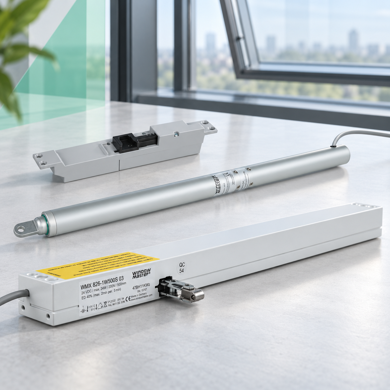
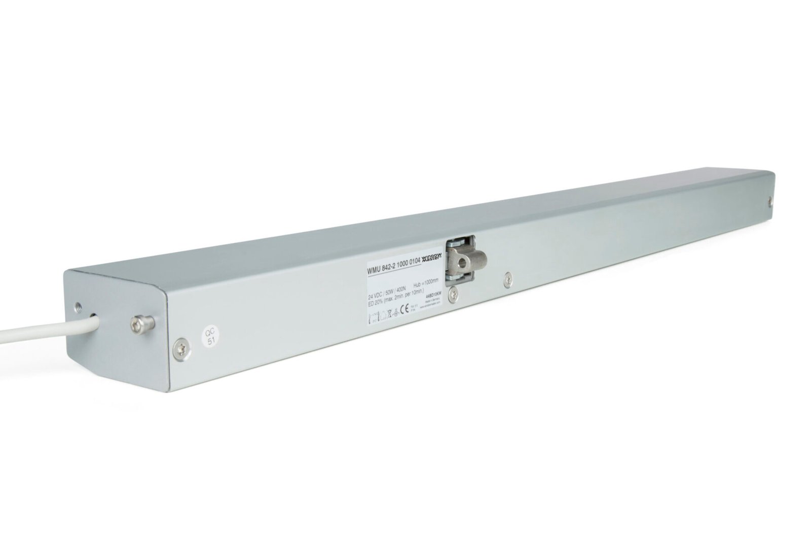
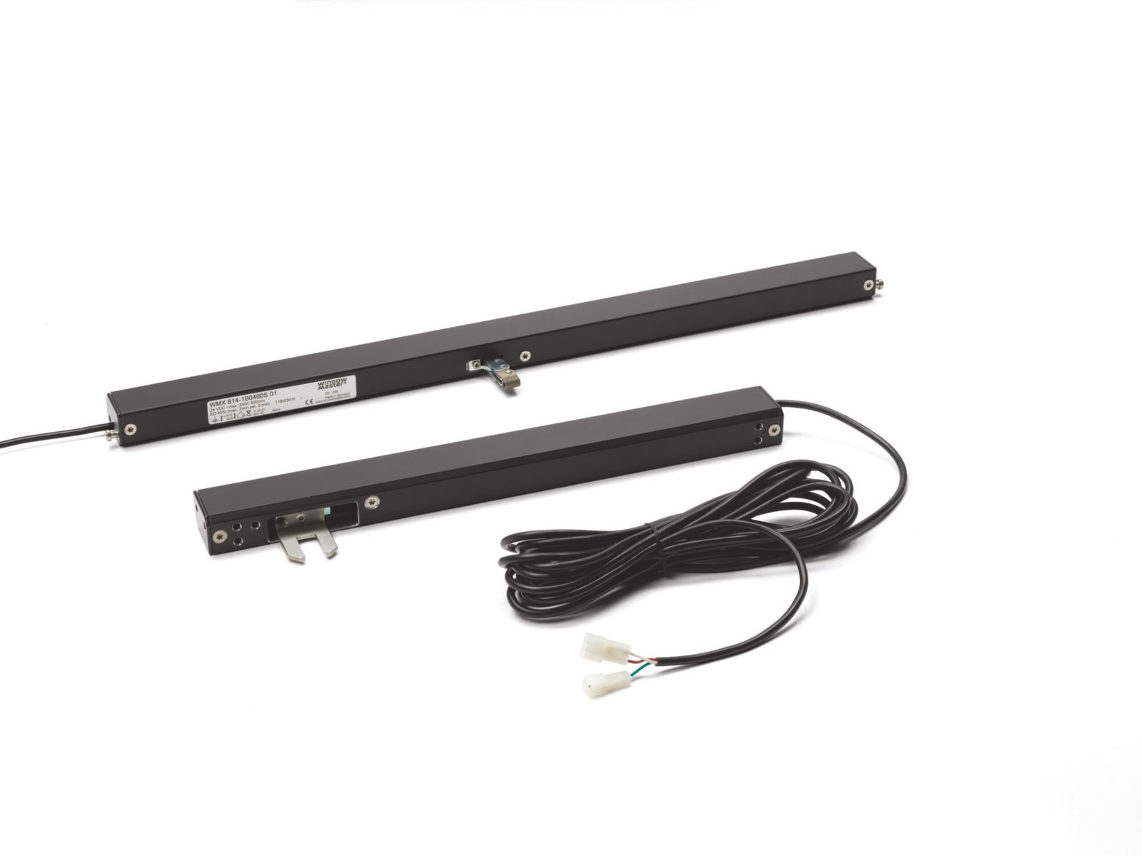
Our range of WindowMaster actuators, which Blue Squared supplies and specifies across Australia, covers most commercial and institutional applications:WindowMaster motor drives

Chain actuators are the most widely used type for top-hung and awning windows. They’re available across a range of chain strokes and forces, in concealed or surface-mounted versions and a choice of finishes, which makes them adaptable to different window profiles and aesthetic requirements.

Spindle actuators suit higher-load applications such as pitched rooflights, where a chain actuator’s stroke and force aren’t sufficient. The trade-off is that a spindle actuator’s housing projects into the room when the window is open, which some designers and clients find visually intrusive,  worth resolving early where roof glazing is visible from below, since a high-capacity chain actuator can sometimes offer a neater alternative.

Louvre actuators are purpose-built for glazed louvre systems rather than adapted from a window actuator, and are selected against the specific louvre hardware being used.

Locking and espagnolette actuators operate multi-point locking windows, relevant where security or air-tightness requirements go beyond a simple opening vent.

WindowMaster ActuatorDoor actuators extend the same automation logic to automated door openings within the same control ecosystem.

Controllers sit behind all of the above. WindowMaster’s comfort-ventilation controllers (the WCC range) and smoke-ventilation panels (the WSC range) manage groups of actuators, handle switch and sensor inputs, and,  where MotorLink communication is used,  provide two-way feedback to the BMS on position and faults, synchronised movement across multiple actuators on the same facade, and an obstacle-detection function that reverses an actuator if it meets resistance while closing.

Each actuator type also has its own bracket and mounting hardware, matched to whether it’s concealed within the profile or surface mounted, and to the specific window or louvre system it’s fitted to. This is worth confirming during specification rather than assuming a bracket will suit whatever window is eventually detailed.


Voltage, wiring and safety

Blue Squared’s actuator range runs on 24V DC rather than mains voltage. This matters in particular on aluminium windows, where the frame itself is a good conductor: extra-low voltage actuation is inherently safer if a cable is ever damaged or snagged during the life of the building. Mains-voltage actuators exist on the market and suit occasional, light-duty operation, but they’re generally avoided for windows expected to open and close regularly, where they’re more prone to overheating.

Wiring routes are worth resolving at specification stage rather than left to site. A window profile can often be used as a concealed conduit for actuator cabling, which avoids surface-mounted trunking later,  but it requires the window or curtain wall fabricator to prepare the profile with grommets and draw wires in advance. Left unresolved, this tends to surface as an unplanned, visible cable run during installation.

Understanding the ventilation strategy an actuator is serving


building ventilation strategy window motors Actuator selection also depends on which natural ventilation principle a window is being used for, since this affects how often and how far the actuator needs to cycle.

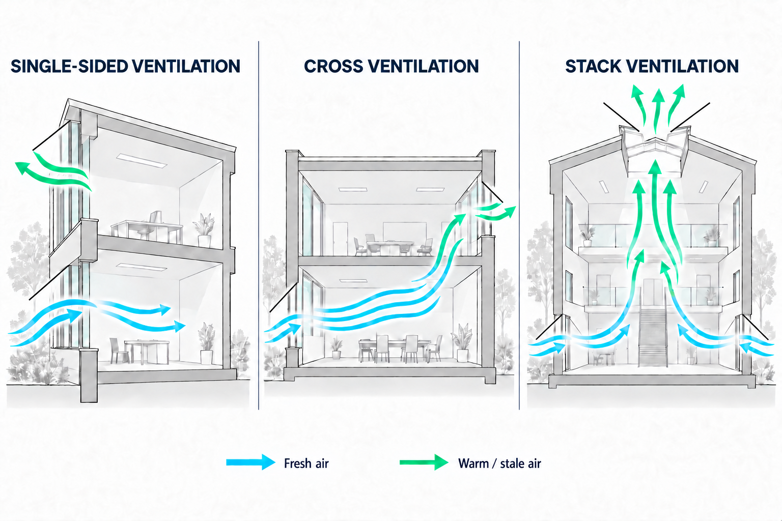
Single-sided ventilation applies to rooms with openings on one side only. In cooler weather, this typically relies on pulse ventilation,  windows opening for short, controlled bursts to refresh the air quickly before closing again, since sustained openings in cold or windy conditions create draughts. This pattern asks more of an actuator’s cycling and control than a window that opens once each morning and closes each evening.

Cross ventilation uses openings on two sides of a space to draw air through the room, driven by the pressure difference between the windward and sheltered sides of the building. Because the windward and sheltered openings usually need to operate to different degrees to balance airflow and minimise draughts, this generally means independently controlled actuators on each side rather than a single shared setting.

Stack ventilation relies on the natural tendency of warm air to rise, drawing fresh air in at lower levels and exhausting it through openings higher in the building. This typically puts actuators at roof or high level, where accessibility for maintenance and safety sensing are different considerations to a low-level window.

Mixed-mode (or hybrid) ventilation switches between natural and mechanical ventilation depending on real-time conditions,  temperature, CO2 and humidity, both inside and out. Here, the actuators and their controller need to coordinate with the mechanical system rather than operate independently, opening and closing windows automatically as conditions change and handing over to mechanical ventilation when natural ventilation isn’t suitable.

In each case, the actuator is carrying out a strategy that a mechanical engineer or facade consultant has designed for that specific building; it’s worth confirming which of these strategies applies before assuming a standard actuator and control setup will suit the application.

Purge ventilation and thermal mass

Many commercial and education buildings use a purge strategy alongside day-to-day ventilation, commonly known as night purging or night flushing. The principle is straightforward: a building’s exposed structure (concrete slabs and columns, for example) absorbs heat during the day, and opening windows or louvres for a set period brings in cooler air that removes that stored heat and re-cools the thermal mass, so the building starts the next day cooler and needs less mechanical cooling to stay comfortable.

Whether that purge period runs overnight or in the hours immediately before a building is occupied is a genuine design decision, not a fixed rule,  it depends on the building’s occupancy pattern, local climate and how the outside air temperature moves overnight compared with early morning. This is exactly the kind of control logic that should be set with the mechanical engineer at design stage, since it determines how the actuators are scheduled and how the controller interacts with the BMS, rather than being left as a default setting.

Where actuators fit in a smoke-control strategy

An actuator carries out the strategy a fire engineer has designed,  it doesn’t set that strategy itself. Where an actuator forms part of an engineered smoke-control strategy,  for example, as part of an automatic opening vent,  its required performance, fail-safe behaviour and interfaces with the fire system are set by the project’s fire engineer and tested against the relevant standard. This is not a decision a product specification can make on its own, and any smoke-control application needs project-specific fire engineering input rather than a generic assumption drawn from another building.

Installation and commissioning

Getting an actuator specified correctly is only the first half of the job; how it’s installed and commissioned affects how reliably it performs for the life of the building. In practice this runs through several stages: design and specification (confirming the actuator, free area and control approach before tender), supply, on-site installation coordinated between the automation specialists and the project’s electrical trade, builder and facade contractor, and finally commissioning,  testing that every actuator operates correctly, that sensor and BMS interfaces respond as designed, and that sign-off documentation is completed before handover.

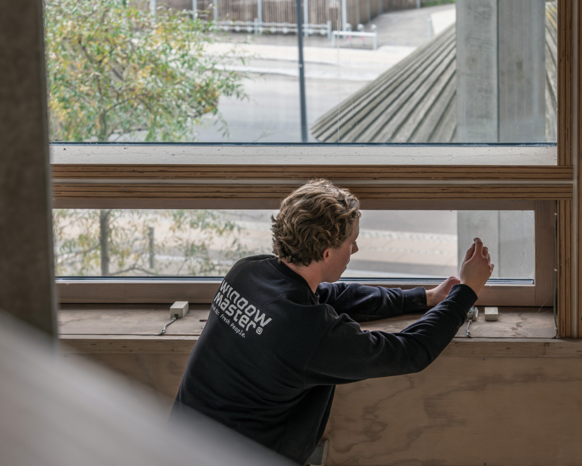
installing a window actuator windowmasterCoordination matters most at the boundaries between trades: who is responsible for the bracket fixings into the window frame, who runs and terminates the cabling, and who tests the interface with the fire panel or BMS. Leaving these questions until installation is where avoidable delays tend to happen.

A practical takeaway for design teams

Before an actuator is selected, it’s worth having answered:

The window or louvre type, opening direction, dimensions and glazing weight. Which ventilation strategy the opening serves,  single-sided, cross, stack or mixed-mode,  and how that affects cycling frequency and control logic. The free area the strategy requires, and whether reveals, sills or adjacent openings affect what’s achievable. Whether the opening is at a height that needs restriction or safety sensing, or is otherwise accessible to occupants. How the system will be controlled,  wall switch, app, BMS, or a combination,  and whether it needs to interface with the fire system. Where the wiring will run, and whether the window profile can be used to conceal it. Which disciplines need to sign off before the design is locked in: the architect on aesthetics and opening type, the facade engineer on loads and window detailing, the mechanical engineer on ventilation strategy, the fire engineer where smoke control is involved, and the electrical contractor on cabling.

Resolving these questions during design, rather than after the facade and window details are finalised, is generally what separates a straightforward installation from one that needs rework on site.

motorised window actuator awning window automated louvre windowsConclusion

A window actuator is a small, mechanically simple-looking product doing a job that depends on a long list of project-specific variables,  the opening, the glazing, the free area required, the ventilation strategy and, on many commercial buildings, the fire strategy. Treating actuator selection as a calculation rather than a catalogue choice is what makes the difference between a system that performs quietly for years and one that causes problems at commissioning.

The team at Blue Squared are at hand to provide guidance, advice and a wide range of cost-effective product, service and installed solutions. Please contact our team at info@bluesquared.com.au.